Description:
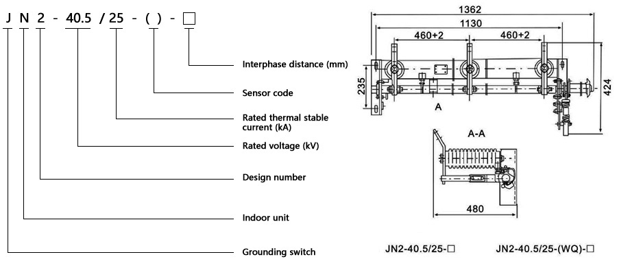
JN2-40.5 indoor high voltage grounding switch is equivalent to adopt IEC129-84 《separation switch and grounding switch》 and IEC694-84 《Common Terms of High Voltage Switchgear and Control Equipment》, according to GB1985-89 "AC high voltage isolating switch and Indoor high voltage electrical appliances designed in the grounding switch for the part of the grounding switch.
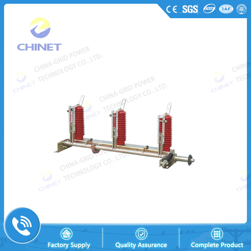
JN2-40.5 type earthing switch is suitable for 35KV and below three-phase AC 50HZ power system, and has voltage monitoring device. Its structure is simple and reliable, its operation force is small, installation and debugging are convenient, usually used for JYNl-40.5 and GFC-40.5 switch. In the cabinet, it can also be used separately.
Structure and working principle:
The grounding switch operating system is designed in the form of spring energy storage, and has a quick closing capability. When the operating link is in trouble, the connecting rod drives the gear on the grounding switch to rotate the main axial direction, and the spring is compressed and stored. Can, reach a certain position (after the spindle starts from the lower limit, 30° exceeds the neutral line), the spring energy is released, and the speed is realized quickly. At this time, the closing speed has no dependence on the operator's movement. This structure ensures the grounding switch. Have the required closing ability
Similarly, in the inter-stage, the operating rod drives the gear on the grounding switch to rotate in the opening direction, and the spring device stores energy. When the spindle rotation angle exceeds 45*, the spring energy storage device releases energy, and the grounding switch is combined
The grounding switch can be configured with different types of high-voltage live display devices according to the requirements of the user. The supporting grounding insulators can be used as insulators of the resin, or DXN passive charging display devices. For the contents of the display device, refer to the installation instructions for the high-voltage live display device
Use conditions:
1.Air temperature: upper limit +40 ° C; lower limit general area -10 ° C, alpine region -25 ° C
2.Note: Storage is allowed at -30 °C. The altitude does not exceed 1000m relative humidity: the daily average is not more than 95%, and the monthly average is not more than 90%
3.The seismicity is not more than 8 degrees
4.There are no fires, exposure hazards, serious contamination, chemical corrosion and severe vibration
5.Note: If the product use conditions exceed the above requirements, the user and the manufacturer negotiate to determine
|
Serial
|
Project
|
Unit
|
Parameter
|
Remark
|
|
1
|
Rated voltage
|
KV
|
40.5
|
|
|
2
|
4s thermal stable current
|
KA
|
25
|
|
|
3
|
Dynamic steady current
|
KA
|
63
|
|
|
4
|
Close short circuit current
|
KA
|
63
|
|
|
5
|
Rated insulation level
|
KV
|
185
|
Lightning impulse withstand voltage
|
|
95
|
Main circuit l min power frequency withstand voltage
|
|
2
|
Secondary circuit lmin power frequency withstand voltage
|
|
6
|
Part of the voltage display device
|
PC
|
≯10
|
|


![]() Inside Road & Administration Industry & Trading Garden,Houshan Industry Area,Fuzhou City,Fujian Province
Inside Road & Administration Industry & Trading Garden,Houshan Industry Area,Fuzhou City,Fujian Province![]() 0591-22806687 0591-22806697
0591-22806687 0591-22806697![]() 0591-22806667
0591-22806667