Description:
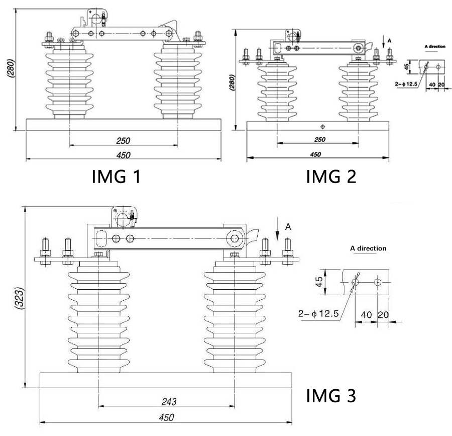
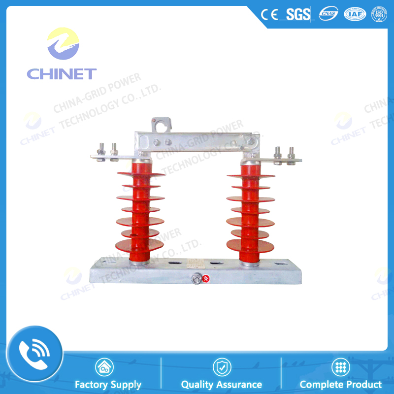
(H) GW9-10 outdoor high-voltage isolator switch is a single-phase AC 50Hz high-voltage switchgear, it is used in the power system with rated voltage of 10kV, it can be used to connect or isolate the power supply when there is voltage and no load, the disconnector is operated with insulated hook bar.
Use environment:
a. The altitude does not exceed 1000 meters;
b. Ambient air temperature: upper limit +40 ° C, lower limit generally -30 ° C, alpine region -40 ° C;
c. The wind pressure does not exceed 700Pa (equivalent to a wind speed of 34m/s);
d. The seismic intensity does not exceed 8 degrees;
e. No frequent and severe vibrations;
f. Ordinary installation sites shall have no gas, vapor, chemical deposits, salt spray, dust and other explosive or aggressive substances that seriously affect the insulation and conductivity of the isolating switch. The anti-fouling type is suitable for heavy pollution areas, but should not cause fire and explosive substances.
Structure and working principle:
The isolating switch is a single-phase structure, and each phase is composed of a chassis, a pillar insulator, a knife, a contact, and the like.
The side of the knife has a screw for adjusting the contact pressure and a spring for pressing, and the upper end is provided with a fixed pull buckle and a self-locking device connected thereto for the opening and closing of the insulating hook rod.
Compared with unmodified products, the new products have the advantages of large contact area, low contact resistance, good electrical conductivity and high mechanical strength.
The isolating switch is generally flip-chip type, and can also be installed vertically or obliquely (the moving contact is below). The M12 bolt is used to fix the chassis to the appropriate position on the cross arm. It should be conveniently pulled on the ground with a gram bar. And close the knife and make sure the chassis does not loosen during operation.
The incoming line should be connected to the static contact side, the outgoing line should be connected to the moving contact side, and the appropriate distance should be maintained between the three-phase switches to avoid short circuit.
|
Type
|
Rated voltage
(KV)
|
Rated current
(A)
|
2S thermal stable current
(KA)
|
Dynamic steady current
(kA)
|
Impact withstand voltage
|
Power frequency withstand voltage
|
IMG NO.
|
Phase to ground
(kV)
|
Circuit-breaker
(kV)
|
Phase to ground
(kV)
|
Circuit-breaker
(kV)
|
|
(H)GW9-12/200
|
12
|
400
|
8
|
20
|
75
|
85
|
38
|
42
|
IMG 1
|
|
(H)GW9-12/400
|
12
|
400
|
8
|
20
|
75
|
85
|
38
|
42
|
|
(H)GW9-12/630
|
12
|
630
|
20
|
50
|
75
|
85
|
38
|
42
|
|
(H)GW9-12/1000
|
12
|
1000
|
25
|
65
|
75
|
85
|
38
|
42
|
|
(H)GW9-12G/400
|
12
|
400
|
8
|
20
|
75
|
85
|
38
|
42
|
IMG 2
|
|
(H)GW9-12G/630
|
12
|
630
|
20
|
50
|
75
|
85
|
38
|
42
|
|
(H)GW9-12G/1000
|
12
|
1000
|
25
|
65
|
75
|
85
|
38
|
42
|
|
(H)GW9-12G/1250
|
12
|
1250
|
31.5
|
80
|
75
|
85
|
38
|
42
|
|
(H)GW9-15G/400
|
15
|
400
|
8
|
20
|
75
|
85
|
38
|
42
|
IMG 3
|
|
(H)GW9-15G/630
|
15
|
630
|
20
|
50
|
75
|
85
|
38
|
42
|
|
(H)GW9-15G/1000
|
15
|
1000
|
25
|
65
|
75
|
85
|
38
|
42
|
|
(H)GW9-15G/1250
|
15
|
1250
|
31.5
|
80
|
75
|
85
|
38
|
42
|


![]() Inside Road & Administration Industry & Trading Garden,Houshan Industry Area,Fuzhou City,Fujian Province
Inside Road & Administration Industry & Trading Garden,Houshan Industry Area,Fuzhou City,Fujian Province![]() 0591-22806687 0591-22806697
0591-22806687 0591-22806697![]() 0591-22806667
0591-22806667