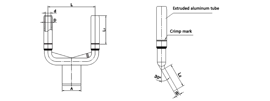
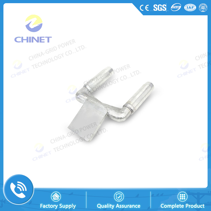
Technology:
|
Type
|
Applicable Conductor Model
|
Main Dimensions (mm)
|
|
d
|
D
|
L1
|
L
|
L2
|
A
|
A
|
|
SSY(G)-185/30-120
|
LGJ-185/25 ~ 30
|
20.5
|
32
|
100
|
120
|
85
|
80
|
12
|
|
SSY(G)-185/30-200
|
20.5
|
32
|
200
|
85
|
80
|
12
|
|
SSY(G)-185/30-400
|
20.5
|
32
|
400
|
85
|
80
|
12
|
|
SSY(G)-240/40-120
|
LGJ-240/30 ~ 40
|
23
|
36
|
120
|
120
|
85
|
80
|
14
|
|
SSY(G)-240/40-200
|
23
|
36
|
200
|
85
|
80
|
14
|
|
SSY(G)-240/40-400
|
23
|
36
|
400
|
85
|
80
|
14
|
|
SSY(G)-300/40-120
|
LGJ-300/25 ~ 40
|
25.5
|
40
|
120
|
105
|
100
|
16
|
|
SSY(G)-300/40-200
|
25.5
|
40
|
200
|
105
|
100
|
16
|
|
SSY-300/40-400
|
25.5
|
40
|
400
|
105
|
100
|
16
|
|
SSY-400/35-120
|
LGJ-400/20 ~ 35
|
28.5
|
45
|
130
|
120
|
105
|
100
|
16
|
|
SSY-400/35-200
|
28.5
|
45
|
200
|
105
|
100
|
16
|
|
SSY-400/35-400
|
28.5
|
45
|
400
|
105
|
100
|
16
|
|
SSY-500/45-120
|
LGJ-500/35 ~ 45
|
31.5
|
52
|
140
|
120
|
130
|
125
|
20
|
|
SSY-500/45-200
|
31.5
|
52
|
200
|
130
|
125
|
20
|
|
SSY-500/45-400
|
31.5
|
52
|
400
|
130
|
125
|
20
|
|
SSY-630/80-120
|
LGJ-630/55 ~ 80
|
36.5
|
60
|
160
|
120
|
130
|
125
|
20
|
|
SSY-630/80-200
|
36.5
|
60
|
200
|
130
|
125
|
20
|
|
SSY-630/80-400
|
36.5
|
60
|
400
|
130
|
125
|
20
|
|
SSY-800/100-200
|
LGJ-800/55 ~ 100
|
40.5
|
65
|
180
|
200
|
155
|
150
|
22
|
|
SSY-800/100-400
|
40.5
|
65
|
400
|
155
|
150
|
22
|

|
Notes:
1.S means device clamp, Y means crimping, S means double conductor, G means copper-aluminum transition, and molecular number means suitable conductor type.The denominator number denotes the distance between two wires, 120 denotes the distance 120, 200 denotes the distance 200, 400 denotes the distance 400, the additional letter A denotes the level (0°), B denotes 30°, C denotes 45° and D denotes 90°.
2.The clamps are also suitable for other types of wires within the outer diameter of the wire, such as: steel core heat-resistant aluminum alloy stranded wire
3.If the distance between the two wires and the size of the terminal plate are different from those in the table, please specify separately when ordering (A*12)

![]() Inside Road & Administration Industry & Trading Garden,Houshan Industry Area,Fuzhou City,Fujian Province
Inside Road & Administration Industry & Trading Garden,Houshan Industry Area,Fuzhou City,Fujian Province![]() 0591-22806687 0591-22806697
0591-22806687 0591-22806697![]() 0591-22806667
0591-22806667